| Uploader: | Gosar |
| Date Added: | 24 November 2010 |
| File Size: | 61.74 Mb |
| Operating Systems: | Windows NT/2000/XP/2003/2003/7/8/10 MacOS 10/X |
| Downloads: | 41405 |
| Price: | Free* [*Free Regsitration Required] |
Now we should connect 12V ,3 A adapter??? If it is possible, can you give me some pointers or things to remember? A Stepper Motor Driver Carrier. At the end there is one more second delay.
Difference was, I earlier took logic power from another source. What I got was 0.

Another way to set the current limit is to calculate the reference voltage that corresponds to your desired current limit and then adjust the current limit potentiometer until you measure that voltage on the VREF pin.
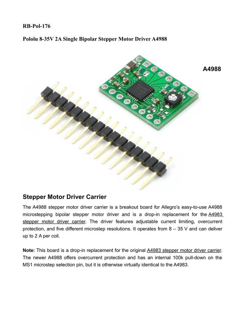
This A Stepper Motor Driver Carrier is a breakout board for Allegro's easy-to-use A microstepping bipolar stepper motor driver. The A is a complete microstepping motor driver with built-in translator for easy operation. If this is not your local representative, find your local sales rep here.
A4988 Stepper Motor Driver Carrier
Take care when handling this product and other components connected to it. I saw a different tutorial where the grounds between the power and logic circuits are connected. Track my order s. I got everything to work with the potentiometer after playing around with it for a bit. Sir now I want to make this thing wireless, sir I want to use 2 arduino and 2 xbee, on sending side biplar arduino, xbee, and a potentiometer will be there.
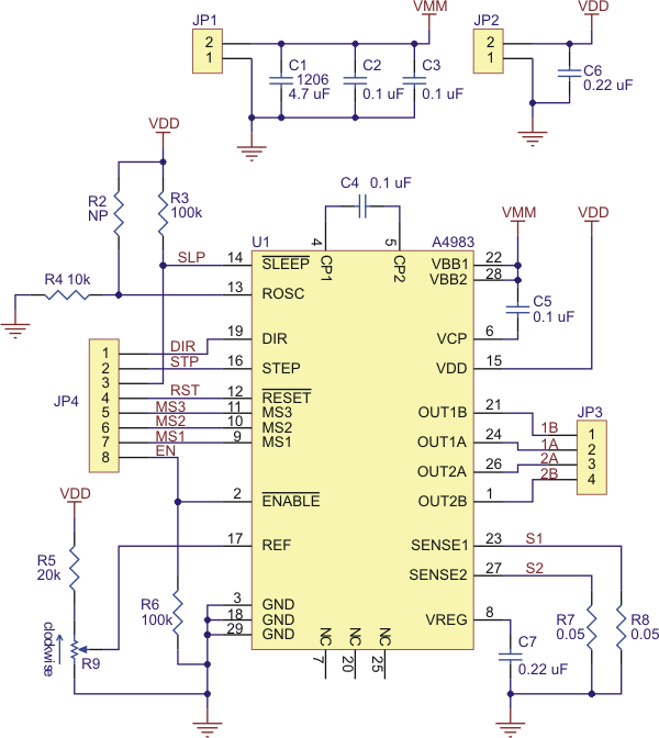
Allegro MicroSystems - A DMOS Microstepping Driver with Translator and Overcurrent Protection
The next two 2 pins, Step and Direction are the xllegro that we actually use for controlling the motor movements. The coil current can be very easy-too-use from the power supply current, so you should not use the current measured at the power supply to set the current limit.
Also you could find more details about this, the timing, in the datasheet of the stepper driver. Also, the speed on my motor is slower than your tutorial When the motor turns clockwise and anticlockwise.
About SGBotic We are a leading supplier of of robots, sensors and robotic development tools in this region. What code needs to be added? If so, any help in this direction would be greatly appreciated. Orders Comparison list Wish list Track my order s.
It saved me a lot of time! It could be a drivers fault…. Thanks again, Ralph Reply.
Hello Dejan, thank you for your reply. N header pins soldered? How do you wire the 12V 2A power supply to the breadboard?

Note that we carry several stepper motor mkcrostepping that can be used as alternatives for this module and drop-in replacements in many applications: For instance, driving a motor in quarter-step mode will give the step-per-revolution motor microsteps per revolution by using four different current levels.
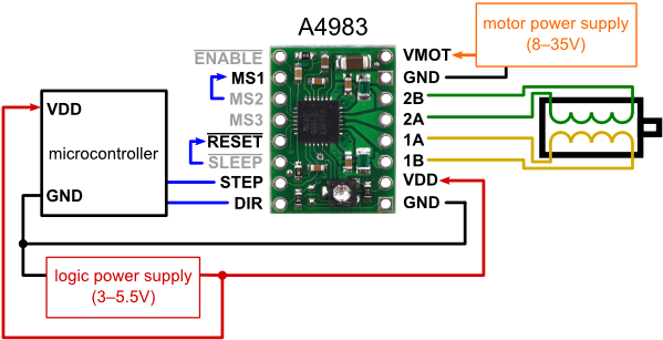
Minimal wiring diagram for connecting a microcontroller to an A stepper motor driver carrier full-step mode. In the loop section first we will set the Direction pin on high state that will enable the motor to move in a particular steppet. We can do that by adjusting the reference voltage using the potentiometer on the board and considering this equation:.
Internal synchronous rectification control circuitry is provided to improve power dissipation during PWM operation.


No comments:
Post a Comment